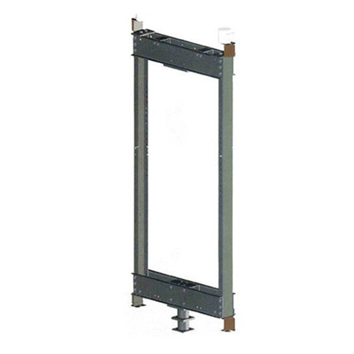
مختلف ٽريڪشن ريٽس لاءِ لفٽ ڪائونٽر ويٽ فريم
تيل جو ڪين
گائيڊ بوٽ
ڪائونٽر ويٽ فريم
ڊوائيس کي لاڪ ڪريو
بفر کي ڇڪڻ وارو آخر
ڪائونٽر ويٽ بلاڪ
معاوضي وارو فاسٽنر
معطلي وارو اوزار (شيو پُلي يا رسي جو معطلي)
اسان توهان جي گهرجن مطابق پڻ ترتيب ڏئي سگهون ٿا
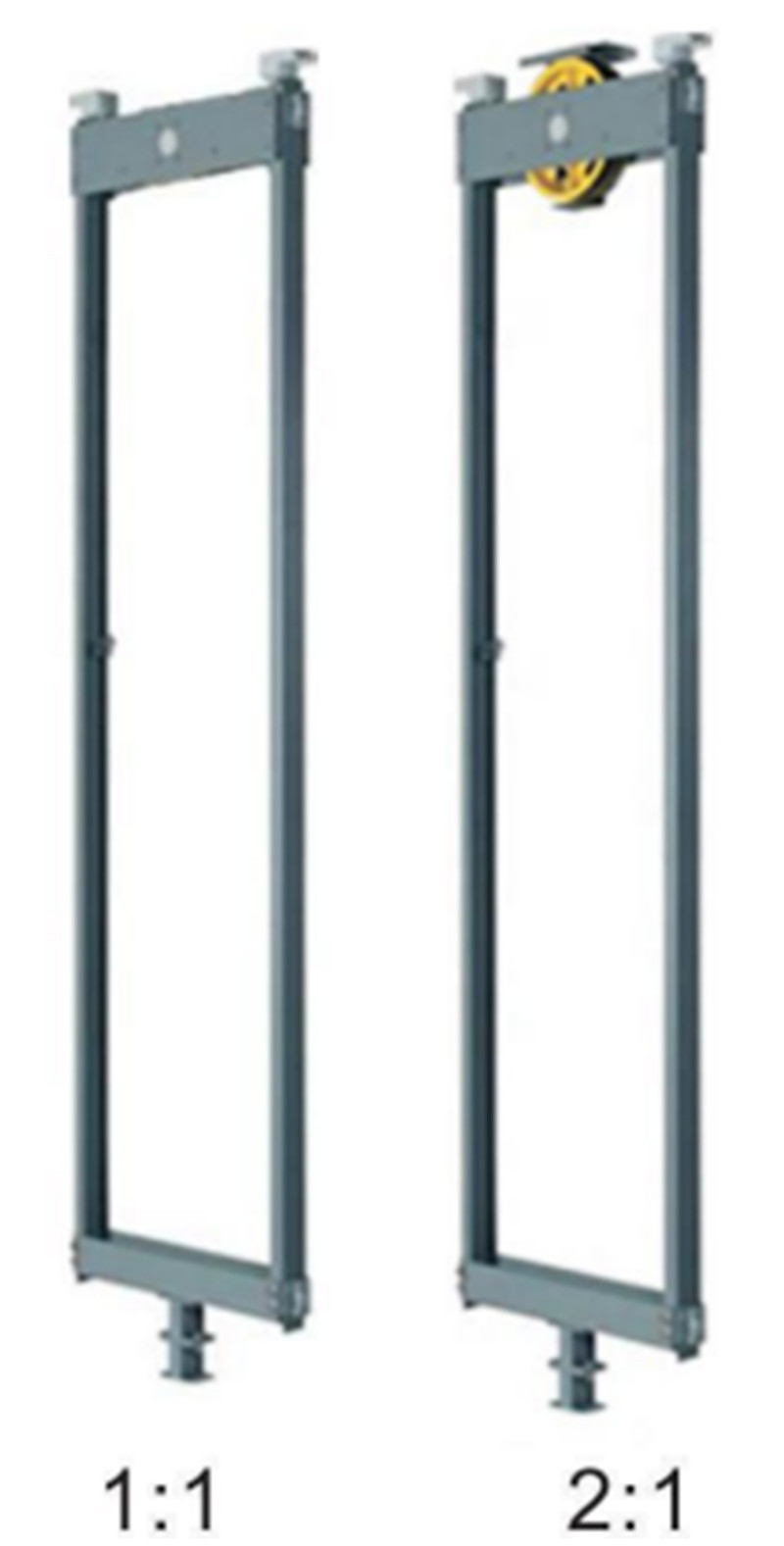
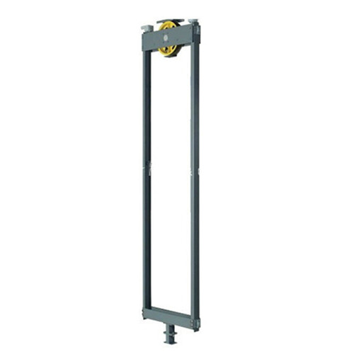
ڪائونٽر ويٽ فريم چينل اسٽيل يا 3~5 ملي ميٽر اسٽيل پليٽ مان ٺهيل آهي جيڪو چينل اسٽيل جي شڪل ۾ فولڊ ڪيو ويو آهي ۽ اسٽيل پليٽ سان ويلڊ ڪيو ويو آهي. مختلف استعمال جي موقعن جي ڪري، ڪائونٽر ويٽ فريم جي جوڙجڪ پڻ ٿوري مختلف آهي. مختلف ٽريڪشن طريقن جي مطابق، ڪائونٽر ويٽ فريم کي ٻن قسمن ۾ ورهائي سگهجي ٿو: 2:1 سلنگ طريقي لاءِ ويل ڪائونٽر ويٽ فريم ۽ 1:1 سلنگ طريقي لاءِ ويل لیس ڪائونٽر ويٽ فريم. مختلف ڪائونٽر ويٽ گائيڊ ريل جي مطابق، ان کي ٻن قسمن ۾ ورهائي سگهجي ٿو: ٽي-شڪل گائيڊ ريل ۽ اسپرنگ سلائيڊنگ گائيڊ بوٽن لاءِ ڪائونٽر ويٽ ريڪ، ۽ هولو گائيڊ ريل ۽ اسٽيل سلائيڊنگ گائيڊ بوٽن لاءِ ڪائونٽر ويٽ ريڪ.
جڏهن لفٽ جو ريٽيڊ لوڊ مختلف هوندو آهي، ته ڪائونٽر ويٽ فريم ۾ استعمال ٿيندڙ سيڪشن اسٽيل ۽ اسٽيل پليٽ جون وضاحتون به مختلف هونديون آهن. جڏهن ڪائونٽر ويٽ سڌي بيم جي طور تي سيڪشن اسٽيل جي مختلف وضاحتن کي استعمال ڪيو ويندو آهي، ته سيڪشن اسٽيل نوچ جي سائيز سان ملندڙ ڪائونٽر ويٽ لوهه جو بلاڪ استعمال ڪيو ويندو آهي.
لفٽ ڪائونٽر ويٽ جو ڪم ڪار جي پاسي تي معطل ٿيل وزن کي ان جي وزن سان متوازن ڪرڻ آهي ته جيئن ٽريڪشن مشين جي طاقت کي گهٽائي سگهجي ۽ ٽريڪشن جي ڪارڪردگي کي بهتر بڻائي سگهجي. ٽريڪشن وائر رسي لفٽ جو هڪ اهم سسپنشن ڊيوائس آهي. اهو ڪار ۽ ڪائونٽر ويٽ جو سڄو وزن برداشت ڪري ٿو، ۽ ٽريڪشن شيو گروو جي رگڙ ذريعي ڪار کي مٿي ۽ هيٺ هلائي ٿو. لفٽ جي آپريشن دوران، ٽريڪشن وائر رسي ٽريڪشن شيو، گائيڊ شيو يا اينٽي-روپي شيو جي چوڌاري هڪ طرفي يا متبادل طور تي موڙي ويندي آهي، جيڪو ٽينسل اسٽريس جو سبب بڻجندو. تنهن ڪري، ٽريڪشن وائر رسي کي اعلي طاقت ۽ لباس مزاحمت جي ضرورت آهي، ۽ ان جي ٽينسل طاقت، ڊگھائي، لچڪ، وغيره سڀ GB8903 جي گهرجن کي پورو ڪرڻ گهرجن. تار رسي جي استعمال دوران، ان کي ضابطن جي مطابق باقاعدي طور تي معائنو ڪيو وڃي، ۽ تار رسي کي حقيقي وقت ۾ مانيٽر ڪيو وڃي.
1. اسڪافولڊ تي لاڳاپيل پوزيشن تي هڪ آپريٽنگ پليٽ فارم قائم ڪريو (ڪائونٽر ويٽ فريم کي کڻڻ ۽ ڪائونٽر ويٽ بلاڪ جي انسٽاليشن کي آسان بڻائڻ لاءِ).
2. ٻن مخالف ڪائونٽر ويٽ گائيڊ ريل سپورٽ تي هڪ مناسب اوچائي تي تار جي رسي بڪل کي ڳنڍيو (ڪائونٽر ويٽ کڻڻ کي آسان بڻائڻ لاءِ)، ۽ تار جي رسي بڪل جي وچ ۾ هڪ زنجير لٽڪايو.
3. ڪائونٽر ويٽ بفر جي هر پاسي تي 100mm X 100mm ڪاٺ جو چورس سهارو ڏنو ويو آهي. ڪاٺ جي چورس جي اوچائي جو تعين ڪرڻ وقت، لفٽ جي اوور ٽريول فاصلي تي غور ڪيو وڃي.
4. جيڪڏهن گائيڊ جوتا اسپرنگ ٽائيپ يا فڪسڊ ٽائيپ جو آهي، ته ساڳئي پاسي جا ٻه گائيڊ جوتا هٽائي ڇڏيو. جيڪڏهن گائيڊ جوتا رولر ٽائيپ جو آهي، ته چارئي گائيڊ جوتا هٽائي ڇڏيو.
5. ڪائونٽر ويٽ فريم کي آپريٽنگ پليٽ فارم تي منتقل ڪريو، ۽ ڪائونٽر ويٽ رسي هيڊ پليٽ ۽ الٽي ٿيل زنجير کي تار جي رسي بڪل سان گڏ لڳايو.
6. ريوائنڊنگ چين کي هلايو ۽ ڪائونٽر ويٽ فريم کي آهستگي سان مقرر ڪيل اوچائي تي مٿي ڪريو. ڪائونٽر ويٽ فريم لاءِ جنهن ۾ اسپرنگ ٽائيپ يا فڪسڊ گائيڊ بوٽ هڪ پاسي آهن، ڪائونٽر ويٽ فريم کي منتقل ڪريو ته جيئن گائيڊ بوٽ ۽ سائڊ گائيڊ ريل هڪجهڙا هجن. رابطو رکو، ۽ پوءِ نرميءَ سان زنجير کي ڍلو ڪريو ته جيئن ڪائونٽر ويٽ فريم اڳ ۾ سپورٽ ٿيل ڪاٺ جي چورس تي مستحڪم ۽ مضبوطيءَ سان رکيل هجي. جڏهن گائيڊ بوٽن کان سواءِ ڪائونٽر ويٽ فريم ڪاٺ جي چورس تي مقرر ڪيو وڃي، ته فريم جا ٻئي پاسا گائيڊ ريل جي آخري مٿاڇري سان ترتيب ڏنل هجڻ گهرجن. فاصلا برابر آهن.
7. فڪسڊ گائيڊ بوٽس لڳائڻ وقت، پڪ ڪريو ته گائيڊ ريل جي اندروني استر ۽ آخري سطح جي وچ ۾ فرق مٿين ۽ هيٺين پاسن سان مطابقت رکي ٿو. جيڪڏهن گهرجون پوريون نه ٿيون ٿين، ته پوءِ ترتيب ڏيڻ لاءِ شيمز استعمال ڪرڻ گهرجن.
8. اسپرنگ لوڊ ٿيل گائيڊ شو کي انسٽال ڪرڻ کان اڳ، گائيڊ شو ايڊجسٽنگ نٽ کي وڌ ۾ وڌ سخت ڪيو وڃي ته جيئن گائيڊ شو ۽ گائيڊ شو فريم جي وچ ۾ ڪو به فرق نه رهي، جيڪو انسٽال ڪرڻ آسان هجي.
9. جيڪڏهن گائيڊ شو سلائيڊر جي مٿئين ۽ هيٺين اندروني استر جي وچ ۾ فرق ٽريڪ جي آخر واري مٿاڇري سان مطابقت نٿو رکي، ته گائيڊ شو سيٽ ۽ ڪائونٽر ويٽ فريم جي وچ ۾ گيسڪيٽ استعمال ڪريو ته جيئن ترتيب ڏئي سگهجي، ترتيب ڏيڻ جو طريقو فڪسڊ گائيڊ شو وانگر ئي آهي.
10. رولر گائيڊ جوتا آساني سان نصب ڪيو وڃي. ٻنهي پاسن جا رولر گائيڊ ريل تي دٻائڻ کان پوءِ، ٻنهي رولرز جي ڪمپريشن اسپرنگ جي مقدار برابر هجڻ گهرجي. سامهون واري رولر کي ٽريڪ جي مٿاڇري سان مضبوطيءَ سان دٻايو وڃي، ۽ ڦيٿي جو مرڪز گائيڊ ريل جي مرڪز سان هم آهنگ ڪيو وڃي.
11. ڪائونٽر ويٽ جي انسٽاليشن ۽ فڪسنگ
① وزن جي بلاڪن کي هڪ هڪ ڪري وزن ڪرڻ لاءِ پليٽ فارم اسڪيل لاڳو ڪريو، ۽ هر بلاڪ جي سراسري وزن جو حساب ڪريو.
② ڪائونٽر ويٽس جي لاڳاپيل تعداد کي لوڊ ڪريو. وزنن جو تعداد هيٺ ڏنل فارمولي مطابق ڳڻيو وڃي:
نصب ٿيل ڪائونٽر ويٽ جو تعداد = (ڪار جو وزن + ريٽيڊ لوڊ × 0.5) / هر ڪائونٽر ويٽ جو وزن
③ضرورت مطابق ڪائونٽر ويٽ جي اينٽي وائبريشن ڊيوائس کي انسٽال ڪريو.